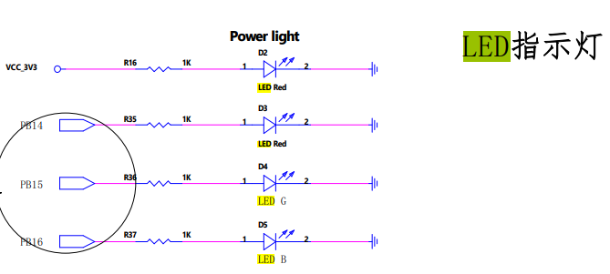
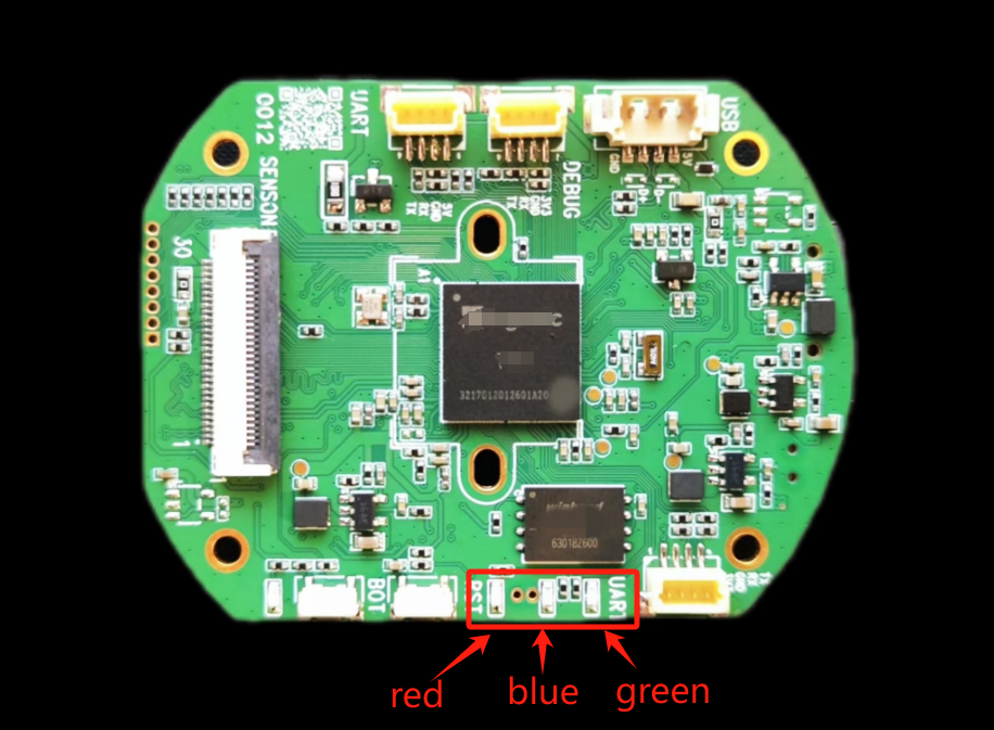
AIOTNIK-ONE开发板预留了三个led指示灯,分别是红绿蓝。用来给用户表示一些功能状态,原理图和实物图如下。


点亮这三个led灯,只需要将灯对应的gpio引脚的电压拉高即可,拉低则灭。以下rgb_led.c是点亮三个led灯的代码。
#include <stdio.h>
#include <stdlib.h>
#include <unistd.h>
#include <string.h>
#include <pthread.h>
#include <sys/time.h>
#include <errno.h>
#include <arpa/inet.h>
#include <fcntl.h>
#include <netinet/tcp.h>

#define PA_GPIO 0
#define PB_GPIO 1
#define PC_GPIO 2

#define PB14 14
#define PB15 15
#define PB16 16

int set_led_color_value(int gpiotype, int colortype, int enable)
{
int fd, fd0;

/* gpio0 = 2*32 + 0 */
int gpio0 = gpiotype*32 + colortype;
char tmp[128];
char on[4] = {0};

//1、导出GPIO
fd = open("/sys/class/gpio/export", O_WRONLY);
if(fd < 0) {
printf("open /sys/class/gpio/export error !");
return -1;
}
sprintf(tmp, "%d", gpio0);
write(fd, tmp, 2);
close(fd);

//2、设置GPIO输入/输出方式
sprintf(tmp, "/sys/class/gpio/gpio%d/direction", gpio0);
fd0 = open(tmp, O_RDWR);
if(fd0 < 0) {
printf("open /sys/class/gpio/gpio%d/direction error !", gpio0);
return -1;
}
write(fd0, "out", 3);
close(fd0);

//3、设置GPIO有效电平
sprintf(tmp, "/sys/class/gpio/gpio%d/active_low", gpio0);
fd0 = open(tmp, O_RDWR);
if(fd0 < 0) {
printf("open /sys/class/gpio/gpio%d/active_low error !", gpio0);
return -1;
}
write(fd0, "1", 1);
close(fd0);

//4、设置输入/输出高低电平
sprintf(tmp, "/sys/class/gpio/gpio%d/value", gpio0);
fd0 = open(tmp, O_RDWR);
if(fd0 < 0) {
printf("open /sys/class/gpio/gpio%d/value error !", gpio0);
return -1;
}
sprintf(on,"%d", enable);
write(fd0, on, strlen(on));

//5、关闭gpio句柄
close(fd0);

return enable;
}


int main()
{

while(1)
{

set_led_color_value(PB_GPIO, PB14, 0);//红灯灭
sleep(1);
set_led_color_value(PB_GPIO, PB14, 1);//红灯亮
sleep(1);
set_led_color_value(PB_GPIO, PB15, 0);//绿灯灭
sleep(1);
set_led_color_value(PB_GPIO, PB15, 1);//绿灯亮
sleep(1);
set_led_color_value(PB_GPIO, PB16, 0);//蓝灯灭
sleep(1);
set_led_color_value(PB_GPIO, PB16, 1);//蓝灯亮
sleep(1);
}
}
示例代码编译
mips-linux-uclibc-gcc rgb_led.c -o rgb_led
将编译出来的rgb_led程序拷贝到板子运行,即可实现rgb三色灯的跑马灯效果。


